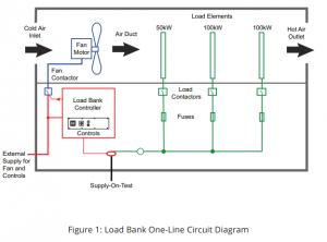
The load group has the characteristics of safety, reliability, convenient operation and long service life. Understanding the layout and function of the control, cooling, and load element circuits is important to understand how the load group operates, to select the load group for the application, and to maintain the load group. These circuits are described in the following sections
Eak load group run overview
The load group receives electricity from the power supply, converts it into heat, and then expels the heat from the unit. By consuming power in this way it places the corresponding load on the power supply. To do this, the load group absorbs a large amount of current. A 1000 kw, 480 v load bank will continue to absorb over 1200 amperes per phase and will generate 3.4 million thermal units of heat per hour.
The load group is typically used
(1) to apply pressure to the power supply for testing purposes, such as periodic testing of the generator
(2) to affect the operation of the prime mover, for example, provide a minimum load to prevent the accumulation of unburned exhaust gas residues on the diesel engine
(3) adjust the power factor of the electrical circuit.
The load group exerts a load by directing current to the load element, which uses resistance or other electrical effects to consume power. Whatever the purpose of the run, any heat generated must be removed from the load group to avoid overheating. Heat removal is usually accomplished by an electric blower that removes heat from the load group.
The load element circuit, the blower system circuit and the device circuit controlling these elements are separate. Figure 1 provides a simplified single-line diagram of the relationships between these circuits. Each circuit is further described in the following sections.

Control circuit
The basic load group control includes the main switch and the switch that controls the cooling system and the load components. Load components are typically switched separately using a dedicated switch; this enables the operator to apply and change the load incrementally. The load step is defined by the ability of the minimum load element. A load group with one 50kW load element and two 100kw elements provides the opportunity to select a total load of 50,100,150,200, or 250KW at a resolution of 50kW. Figure 2 shows a simplified load group control circuit.
Notably, the Load Group Control Circuit also provides power and signaling for one or more overtemperature sensors and air fault safety devices. The former is designed to detect overheating in a load group, regardless of the cause. The latter are switches that are turned off only when they sense air flowing over the load element; if the switch is kept on, electricity can not flow to one or more load elements, thus preventing overheating.
The control circuit requires a single-phase voltage source, typically 120 volts at 60 hertz or 220 volts at 50 hertz. This power can be obtained from the power supply of the load element by using any necessary step-down transformers, or from an external single-phase power supply. If the load group is configured for dual-voltage operation, a switch is set in the control circuit so that the user can select the appropriate voltage mode.
Input power line side of the fuse protection control circuit. When the control power switch is closed, the control power indicator lights up to show the existence of power supply. After the control power supply is available, the operator uses the blower start switch to start the cooling system. After the blower provides the appropriate air flow rate, one or more internal differential air preset switches detect the air flow and are close to placing a voltage on the load circuit. If there is no“Air fault” and proper airflow is detected, the air switch will not be turned off and the indicator light will be turned on. A master load switch is usually provided to control the overall function of a particular load element or group of switches. The switch can be used to safely reduce all applied loads, or as a convenient means of providing a full or“Spread” load to the power supply. Load stepping switches measure individual components to provide the required load.
Post time: Jul-10-2024


